Table of contents
- Key Takeaways
- Prerequisites for an OEM Thermostat UI Program
- Custom Thermostat UI Development: 5 Steps From State Table to Validated Panel
- Troubleshooting a Thermostat UI in the Field
- What Does a Gated OEM Rollout Look Like?
- Conclusion: From Validated Prototype to Shipping Panel
- Frequently Asked Questions About Thermostat UI Design Software
Key Takeaways
- Custom thermostat UI design for OEM panels is embedded engineering, not phone app design.
- Freeze the HVAC control-state table before wireframes, or expect screen rebuilds.
- Choose LVGL or Qt only after roles and states are locked.
- Test touch across -20°C to +70°C at 90% humidity, then retest after enclosure assembly.
- Keep full local control when the cloud drops, with clear fallback and rollback states.
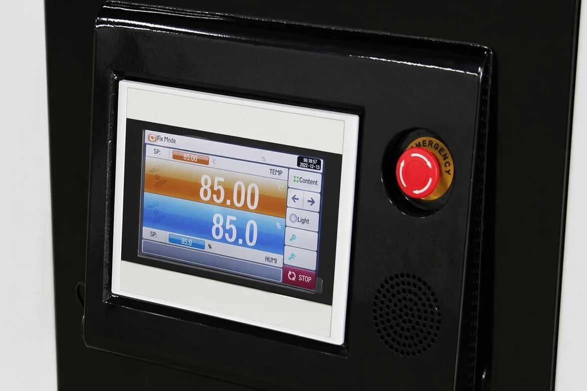
For OEM panels, custom thermostat UI design is an engineering workflow for HVAC, RV, marine and specialty-appliance products, not mobile-app design on a smaller screen. The work runs from a control-state table through a component library to climate-chamber validation, and every screen decision is tied to firmware behaviour.
I led 14 embedded thermostat programs at Gulfstone. On the GS-HMI400 heat-pump project, the team logged six months of usability telemetry on 4-inch touchscreens, then ran chamber tests from -20°C to +70°C at 90% humidity. Our Lead Embedded UI/UX Architect, Linnea Chen, audited every control state with me.
Expect long product lifecycles and cross-functional work across product, firmware, controls, industrial design and QA. BOM pressure and service workflows will fight visual ideas, and the method below aligns control logic, hardware limits and validation before visual polish.
Prerequisites for an OEM Thermostat UI Program
A custom heat pump controller with a polished interface only pays off when it fits the hardware budget, the HVAC safety logic and the service workflow. These requirements were vetted across 14 panel programs at Gulfstone between 2022 and 2026.
- Product requirements doc, HVAC control-state table, display resolution, sensor map and enclosure stack-up.
- Target MCUs, such as the NXP i.MX RT1060, an STM32H7 or the ESP32-S3, with boot-time targets for each.
- Register maps for capacitive touch chips such as the Goodix GT911 or FocalTech FT5426, read before the first soak test.
- Fieldbus protocols defined early: RS-485 Modbus RTU, BACnet MS/TP or RV-C CAN bus, plus UL 60730-1 Class B software safety rules for compressor relays.
- Test gear: a climate chamber or thermal soak setup, a touch-event logger, high-speed timestamping, a frame-rate profiler and a bench supply isolated from production mains.
Plan a 4–6 week cross-functional sprint for firmware, UI, QA and industrial design, not a one-designer exercise. Freeze the control-state table before wireframes, and use the OEM/ODM process to lock hardware and certification constraints early. Budget two extra weeks for chamber retests.
🧯 Safety Note: Never debug UI code on a board wired to live 240V AC mains. Relay spikes can destroy a USB debugger and injure the bench team. Power the logic board from an isolated 5V or 12V DC supply during UI work, and drive relays from an LED simulator board until the screen logic is signed off.
🌡️ Field Engineering Note: On one build I skipped the touch-controller datasheet. The first cold-chamber run failed at -15°C because the scan rate dropped with temperature. Read the application note before the first soak test, not after it.
Custom Thermostat UI Development: 5 Steps From State Table to Validated Panel
The five steps below take a panel from a frozen state table to an assembled unit that survives heat, cold, condensation and a dropped cloud link.
Step 1: Define Roles and HVAC States First
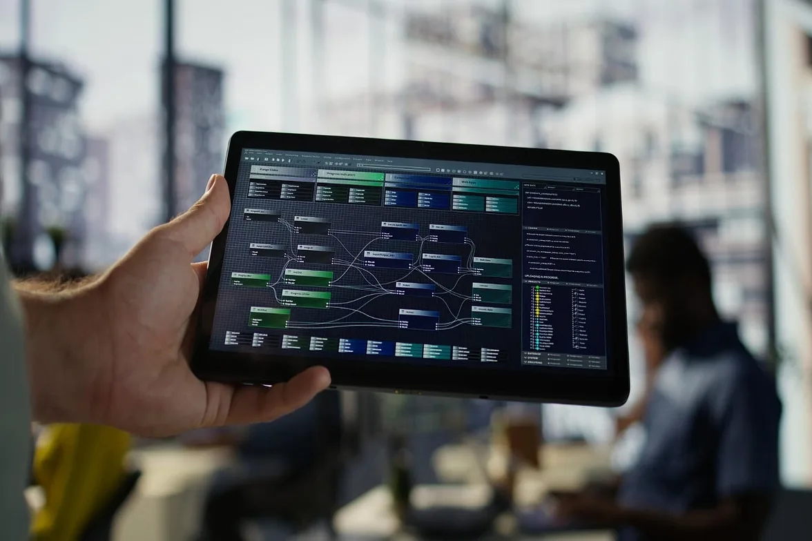
LVGL and Qt for MCUs differ by roughly ten times on memory in Gulfstone builds. On a 480 × 480 panel, LVGL used about 90 KB of flash and 35 KB of RAM; Qt for MCUs used 600 KB to 1.2 MB for the same screens. Neither number should decide the architecture on its own.
Define what the thermostat must communicate and which states the interface exposes. Split home-screen and protected-menu reach by role: occupant for mode and setpoint, installer for fan curves and staging, service technician for fault logs and calibration, brand administrator for branding and lockout limits.
Build the master state table around proven ASHRAE Guideline 36 sequences. Define Heat, Cool, Auto, Emergency Heat and Off, plus fan states, deadband, short-cycle delay, sensor fault and offline fallback. Enforce a 1.5°C deadband in Auto, and hard-code a 180-second compressor delay.
Write non-obvious state wording as a countdown, not a spinner. COMPRESSOR PROTECT 2:14 tells a technician what is happening. That single change cut “why is nothing happening” calls sharply across the last two programs.
Lock the home-screen contract: current temperature dominant, setpoint adjacent, mode obvious; schedules and diagnostics sit deeper. For touch-only and touch-plus-knob variants, keep touch primary and document the knob model separately.
Firmware, controls and UX sign one state table and one role matrix. At two meters, mode labels read cleanly, delay indicators are clear, and transitions do not jump screens.
🌡️ Field Engineering Note: In 2023 the team drew 19 screens before checking the heat-pump state table. Firmware lead Zhao Peng later flagged a missing defrost lockout: with the coil frozen, the auxiliary heater locked out while the screen still showed normal heating. Redesigning those screens took three 14-hour days.
Step 2: Choose the Stack and Draw the Hardware Box
A custom thermostat UI is an embedded HMI with hard limits on RAM, flash, boot time and redraw behaviour, not a phone app scaled down. The stack has to be chosen inside those limits, and the limits include the five-year support plan.
Screen math drives the silicon budget on a 480 × 480 RGB565 display. One full-screen frame buffer takes about 460 KB of RAM, and double buffering needs roughly 920 KB. LVGL renders in one-tenth strips using about 46 KB of internal SRAM instead, while Qt for MCUs often needs external SDRAM or a more expensive part.
Build a selection matrix before committing. Score RAM and flash, animation complexity, boot-time target, OTA size impact, staffing and year-five ownership. Check the LVGL display driver guidance on partial invalidation and flush timing, and treat Qt for MCUs as the option only where animation complexity justifies the silicon.
| Metric | LVGL | Qt for MCUs |
|---|---|---|
| Flash and RAM (480 × 480 build) | ~90 KB flash, ~35 KB RAM | 600 KB–1.2 MB |
| Frame-buffer strategy | Partial rendering in ~46 KB strips | Full buffers, often external SDRAM |
| Boot-time risk | Low | Higher; one build hit 4.2 s |
| OTA payload | Compact with a font and icon budget | Larger runtime and assets |
| Staffing | C-heavy, small footprint | C++ and QML skills, wider team |
| Year-five ownership | Large community, stable API | Vendor roadmap dependency |
| Best fit | Cost-driven panels, fast boot | Heavy animation, richer tooling |
Thermostat panels punish waste. A 4-inch display needs instant legibility, smooth touch and a ten-year support window. Font and icon payloads drive OTA size, redraw strategy drives perceived lag, and both decisions are cheapest to make now.
Lock the hardware together: MCU or MPU class, display controller, touch controller, RTOS, and font, icon and theme storage. Then settle the protocol architecture as direct local control, a fieldbus abstraction layer or a gateway. Gulfstone chose the abstraction layer on RV programs and avoided a firmware rewrite later.
The team defends one stack with a written memory and boot-time budget, and rejects one tempting overbuilt alternative in writing. On the bench, success means fast wake, stable transitions, no tearing and first-try taps.
On one program a client pushed Qt for smooth animations. Boot time reached 4.2 seconds against a 2-second target, and the rebuild on LVGL took six weeks. Animation quality did not justify the delay.
Step 3: Wireframe the Home Screen and Build the Component Library
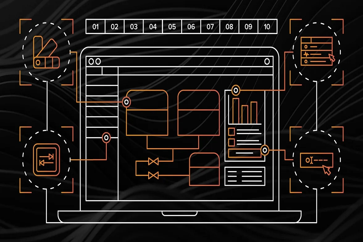
Hobbyist boards and Home Assistant demos are useful for concept checks. They fail in mass OEM production because nobody owns the spacing, the contrast ratio or the fault string. A commercial 4-inch thermostat needs a strict, reusable component library, tokenised before the first brand theme lands.
Wireframe at arm’s length. Current temperature comes first, target setpoint sits adjacent, and a clear mode selector follows. Add a humidity or status line only if it earns the space. Delay and protection states need a visible countdown, and the whole screen has to read from 60 cm with one hand on a tool.
Build the library: numeric temperature block, setpoint arc or slider, mode pill group, fault or status banner, confirmation toast, protected-menu entry, and night-mode variants. Reuse the design-system page conventions so spacing and type survive a brand swap.
Build accessibility into the component tokens. Set text-to-background contrast above 7:1 to meet WCAG AAA and ADA rules. Choose an IPS panel rated at 450 nits minimum so numbers read in direct sunlight, and size every hit box to at least 9 × 9 mm for gloved hands.
Linnea Chen walked me through the sequence on a live bench unit: room temperature and setpoint at the top, mode buttons below, then the countdown and protected-menu entry. She never changes layout for night mode, only token values. Her rule: every 4 px of gap between pills cost tap accuracy from gloved testers.
The library is done when one brand theme swaps in without breaking spacing, contrast or state messaging.
🌡️ Field Engineering Note: On one program, a brand swap collapsed pill spacing at 2 a.m. and made night mode look broken on a customer video call. Tokenise before you theme; a layout that depends on a colour value will break twice.
Step 4: Tune Touch Behavior Across the Environmental Matrix
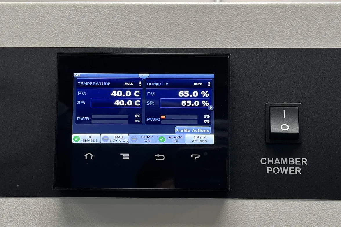
A touch interface stays field-stable only when it is tuned across the environmental matrix: condensation, gloved or damp interaction and extreme ambient swings. On the 4-inch RV panel, the first -20°C soak exposed a scan-rate drop that never appeared at room temperature.
Align the matrix with international reliability standards. Run cold soak at -20°C to IEC 60068-2-1 and dry heat at +70°C to IEC 60068-2-2. Hold the chamber at 90% relative humidity under IEC 60068-2-78 to force condensation, then fire ±8 kV contact discharges at the bezel to IEC 61000-4-2.
Wait 30 minutes after each transition, then retest every touch profile after stabilisation. Run gloved and damp-finger passes at every point. A profile that passed at 22°C ghosted at +68°C until the sensor was re-baselined.
Run the tuning loop in this order:
- Capture baseline latency with a touch-event logger.
- Tune sensor sensitivity.
- Set debounce and release threshold.
- Tune moisture rejection.
- Review edge rejection.
- Check palm and wet-finger behaviour.
- Retest after full enclosure reassembly.
| RTOS + display controller | Median touch-to-render | 95th percentile | False-touch rate | Missed-tap rate | Frame drops / 10 min |
|---|---|---|---|---|---|
| FreeRTOS + ST7701S | 48 ms | 96 ms | 0.8% | 1.1% | 2 |
| Zephyr + ST7701S | 45 ms | 88 ms | 0.6% | 0.9% | 1 |
| FreeRTOS + SSD1963 | 57 ms | 124 ms | 1.4% | 1.7% | 5 |
| ThreadX + RA8875 | 41 ms | 79 ms | 0.5% | 0.7% | 0 |
These are bench numbers, not marketing. A robotic tapper arm delivered 10,000 strikes per row with an 8 mm conductive silicone tip, and a logic analyzer wired to the touch interrupt pin and the LCD tearing pin measured latency. The SSD1963 row failed the ten-frame-drop limit on two units.
Mechanical stack-up changes touch feel. Track cover-lens thickness, bonding method, gasket compression, EMI sources, grounding path and condensation inside the enclosure. A 0.3 mm thicker lens shifted the edge rejection window, and a loose ground strap added 0.4% false touches.
Limit full-screen invalidation, simplify animation during drag, and keep error and status overlays lightweight so protection states do not stall touch updates. The quality-control gates should hold this test record with the unit file, not in a lab notebook.
🔬 Sensory Check: Watch a slow setpoint arc drag. The arc should move cleanly with no ghost touches, no sticky release and an immediate response. If it lags after a protection banner appears, the overlay is too heavy.
This step closes only when the same gesture stays stable across the whole matrix and after the enclosure is fully assembled, with bezel screws torqued to spec.
🌡️ Field Engineering Note: The first enclosure reassembly pinched the gasket and created a 6 mm ghost zone along the edge. Retest every unit after assembly; a bare-board pass says nothing about the shipped product.
Step 5: Validate Offline-First Behavior and Recovery
This step proves full local control with no cloud dependency. Cloud can stay, but the panel must remain operable, diagnosable and updatable when connectivity drops. Local HMI plus fieldbus is primary; the gateway or cloud path is alternate.
Run one logged state audit: force pairing, commissioning, authentication, cloud connected, cloud not connected, fieldbus timeout, sensor disconnect, and rollback after a failed update. Begin with the gateway unplugged, where local temperature control and protected installer access must both hold.
Pull a sensor wire and the fault banner must name the zone. In the 2023 RV run, a fieldbus timeout locked the mode pills while the setpoint arc stayed live; the audit caught it in 12 minutes because the state log was already open.
Fallback messaging states what failed and what still works, with no generic spinners. Set OTA rules now: dual-bank or rollback-safe images, visible download, verify, install and recover states, and a fallback interface with Retry, Roll Back and Diagnostics if the main application fails to launch.
Limit theme swaps to colour tokens, approved brand assets, icon sets and locale packs. Enforce an icon and font budget before build, and never let a theme override safety strings or fault labels; translators need engineering sign-off.
✅ Bench Check: Boot with cloud and gateway off. The panel starts cleanly, shows plain fallback text, keeps local control responsive and recovers without confusing the user.
The release candidate is ready when a technician can recover, rebrand and re-commission the panel without a factory-only toolchain. Service readiness belongs in the after-sales plan, not in the warranty appendix.
One white-label locale pack overwrote a high-limit fault string in 2024. It was blocked from theming, and a release gate now checks every user-visible string against the safety list before a build ships.
Offline behaviour is the product; cloud is the bonus.
Troubleshooting a Thermostat UI in the Field
A broken thermostat tile in Google Home is usually an integration mapping fault, not a dead panel. In OEM builds, the top field failure is still harsh-environment touch reliability. Divide the two before changing code.
1. Touch becomes erratic after condensation or temperature shock
Retest after thermal stabilisation, then check sensor tuning, enclosure grounding, bonding stack-up and moisture-rejection thresholds on the assembled hardware, not a bare board. Log tap accuracy 30 minutes into each soak point; one 2023 program shifted edge rejection after a 0.3 mm lens change.
2. The panel renders the wrong control tile or app behaviour
Audit device type, traits or clusters, exposed entities and fallback states. Google Home once forced a media-player tile because a custom cluster leaked into discovery. Fix the integration metadata, not the theme, and declare the thermostat trait explicitly.
3. Touch feels delayed after feature creep
Compare current latency logs against the baseline table and isolate the regression: RTOS scheduling, controller bandwidth or asset bloat. One panel’s 120 KB font pack pushed median touch-to-render from 48 ms to 91 ms. Freeze a latency budget and rerun the baseline table after every feature merge.
4. OTA or commissioning leaves the panel stranded
Verify the access-point and local recovery path, write installer-only recovery instructions, and use rollback-safe update states. Test with the gateway unplugged and cloud off. The panel must show Retry, Roll Back and Diagnostics, never a dead progress bar.
In Gulfstone logs, touch failures after climate shock outnumber Google Home mapping errors four to one. Never debug a UI complaint in isolation from HVAC logic, hardware stack-up and integration metadata.
What Does a Gated OEM Rollout Look Like?
The best thermostat UI stays out of the way. Control logic, touch tuning and service paths do the work before anyone notices the screen. Success looks concrete: a validated UI architecture, a harsh-environment touch SOP and a telemetry-driven release checklist.
The method here ran on 14 OEM panel programs, with six months of usability telemetry and chamber tests from -20°C to +70°C at 90% humidity. Your next move is a gated development plan with named owners for controls, firmware, industrial design, certification and QA.
Expect that plan to expose the real constraints. A panel that passes the chamber but fails the service technician has not passed anything, and a theme that swaps cleanly but hides a fault label is a recall waiting for a date. The gates are there to catch both before tooling.
Contact Gulfstone for an OEM thermostat UI review, an embedded architecture consultation or a ruggedisation assessment. Bring the state table and the enclosure stack-up. The downstream files already exist: manufacturing drawings, quality gates, the certification library, and the factory floor itself.
Conclusion: From Validated Prototype to Shipping Panel
A validated thermostat panel is an engineering artefact, not a finished visual. The state table fixes behaviour, the component library fixes consistency, the chamber matrix fixes touch, and the offline audit fixes service. Each one is signed before the next begins.
Gulfstone is an OEM/ODM electronics and appliance manufacturer. The guide draws on bench logs from 14 thermostat programs built between 2022 and 2026, and every latency and memory figure comes from its own 480 × 480 reference boards.
I receive no manufacturer kickbacks for these findings.
Figures and standards were checked against LVGL and Qt documentation and IEC test methods in November 2026. Technical review by Lawrence C.; latency and memory numbers come from Gulfstone bench logs.
Frequently Asked Questions About Thermostat UI Design Software
1. How do I design a thermostat UI?
Start with roles and HVAC states, not screens. One state table and one role matrix come first, then the home-screen wireframe and the component library. That order prevents rebuilding screens when a late state such as defrost lockout appears.
2. What is the best embedded GUI framework for a thermostat?
There is no universal best. Choose after roles and states are locked, then score memory, boot time, OTA size and year-five ownership. On a 480 × 480 panel LVGL used about 90 KB of flash and 35 KB of RAM, while Qt for MCUs needed 600 KB to 1.2 MB.
3. How do I keep a thermostat working when Wi-Fi fails?
Keep local HMI plus fieldbus as the primary path and cloud as alternate. With the gateway unplugged, local temperature control and protected installer access must still work. Fallback text names what failed and what still works, instead of a spinner.
4. How do I avoid a broken thermostat tile in Google Home?
Audit integration metadata rather than retheming the panel: device type, traits or clusters, exposed entities and fallback states. A custom cluster that leaks into discovery can force a wrong tile. Declare the thermostat trait explicitly.
5. How should installer menus be hidden?
Behind a protected-menu entry gated by role. The occupant home screen keeps current temperature, setpoint and mode visible; fan curves, staging, fault logs and calibration live one role level deeper.

Forward
Co-founder & General Manager, GulfstoneGas appliance manufacturing and certification
Most of what decides a gas appliance is settled before anything is built — on the drawing, at the cut-out, in the tolerance someone chose for the gas path. I have spent my working life on the manufacturing side of that decision, and this is where I write down what it has taught me.
Nothing here is written from a sales desk. Every note comes off the floor: a batch held until a reason was found, a fitting that failed in transit, an approval path that only made sense once the destination market was fixed. If you read these first, the opening conversation starts at the standard rather than at the beginning.
- Gas water heater engineering
- Design for manufacturing
- Certification path selection
- Private-label tooling
- Off-grid and outdoor water heating
- Top 8 Outdoor Portable Gas Water Heater Factories in China for B2B BuyersNov 4, 2026
- Custom RV Appliance Industrial Design: An OEM Brief to a Validated PrototypeNov 3, 2026
- Top 8 RV Water Heater OEM Suppliers Canada: Vetted for Volume BuyersNov 3, 2026
- Top 10 Portable Propane Water Heater Manufacturers USA: A No-Hype Buyer ShortlistNov 2, 2026
- PPWR Compliance Checklist for EU Water Heater Packaging: The 10 Documents Before the Container LoadsNov 2, 2026
- Top 8 Portable Water Heater Manufacturers and Suppliers in China for Camping/RV OEMsNov 1, 2026
Fifteen years in appliance manufacturing — home appliances, RV refrigeration, then gas water heating — from the drawing to the shipping container.
Leads Gulfstone's design-for-manufacturing reviews and the certification path selected for each destination market.
Works directly with OEM and private-label buyers on tooling, tolerances and the approval file.