Table of contents
- Key Takeaways
- Why Does RV Shore Power Fail Before the Appliances Do?
- Prerequisites: Instruments and Access for Shore-Power Testing
- RV Dirty Power Diagnosis: 4 Steps From Pedestal Test to Signed Commissioning
- Step 1: Test the Pedestal Under Load With a True-RMS Meter
- Step 2: Split the Fault Tree Between Source and Coach
- Step 3: Match the Protection Stack to the Measured Fault
- Step 4: Install and Commission the Converter/Charger
- Troubleshooting: What Each Symptom Means and What to Do Next
- Where Does the SOP Belong in an OEM Build Packet?
- Frequently Asked Questions About RV Shore Power Voltage Regulation
Key Takeaways
- RV dirty power is a fault cluster, not a surge. It covers sustained sag, sustained overvoltage, an open neutral, waveform distortion, transient spikes and harmonic or ripple contamination.
- Split the service before anything else. A 30A RV service is single-leg 120V; a 50A service is split-leg 120/240V with two 120V legs. Every threshold below depends on that split.
- No-load readings hide the fault. A true-RMS meter under a known resistive load shows a sag or a floating neutral that a polarity check passes.
- Disconnect on loaded voltage below 104V or above 132V, reverse polarity, an unstable neutral, or heat-damaged connectors.
- A spike-only MOV is not an EMS. It does nothing for sustained sag, an open neutral or waveform distortion. For an open neutral, the EMS is the first answer.
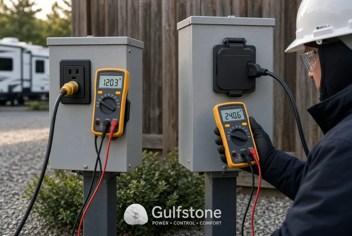
RV shore power voltage regulation is the work that sits between a campground pedestal and the appliances inside the coach: measure the supply under load, find where the voltage or the wiring fails, then fit protection that answers that specific fault. It is not utility-wide voltage theory.
Dirty power reaches a coach as a cluster of faults: a sagging leg, a reversed neutral, a clipped sine wave, a transient spike. Each one damages a different thing, and each one needs a different answer.
This SOP comes from shore-power commissioning and appliance testing at the Foshan lab, plus anonymised service-depot findings from coaches that failed on the road. It starts with measurement under load, not with an app screenshot.
Budget half a day for testing on a coach that is already sited. Budget a full day for a hardwired retrofit and commissioning.
Why Does RV Shore Power Fail Before the Appliances Do?
An RV pedestal, a shore cord, a transfer switch and a main panel are four places a voltage fault can enter the coach. The appliance sits at the end of that chain and is usually the first thing blamed for it.
Voltage falls, demand stays, current climbs. Motors and compressors run hotter at the same workload, and control electronics see a supply outside their design window for hours at a time.
Three anonymised depot failures traced back to that pattern: a ruptured control-board capacitor, a compressor burnout, and repeated thermal overload trips below the safe voltage range. None of them was an appliance defect.
NFPA 1192 treats neutral faults as a safety issue inside the vehicle, which is why an open neutral is a stop-work condition rather than a nuisance. NFPA 70, the National Electrical Code, sets the premises-side rules a pedestal is supposed to meet.
Prerequisites: Instruments and Access for Shore-Power Testing
The kit below came out of four commissioning jobs: two coach platforms and two rebuilt pedestals. On the last of them, an averaging meter missed a 4V sag, so the meter on this list is true RMS and nothing else.
The National RV Training Academy pedestal walk-through above shows the sequence on a live site; the checklist below is the same order, with the thresholds written down.
- True-RMS multimeter with min/max capture. An averaging meter reads a distorted waveform as a healthy number, which is exactly the failure this SOP exists to catch; the Fluke true-RMS explainer covers why the two disagree.
- Clamp meter for loaded current on each leg.
- Known resistive load bank, or two 1,500W portable heaters. Skip hair dryers: their elements drift as they heat and the load stops being repeatable.
- IR thermometer for plug-face and breaker temperatures.
- Torque driver set to the lug values printed on the panel label.
- PPE: Class 0 gloves, safety glasses, non-conductive mat.
- Coach one-line diagram, with breaker sizes marked.
- Oscilloscope with a CAT III differential probe or an isolation transformer. Never clip a scope ground to a live neutral.
Access matters as much as the kit: the pedestal breaker, the main panel, the transfer-switch location, the inverter/charger wiring diagram, and permission to stage a 30A or a 50A load on site.
⚠️ Safety first: Lock out the pedestal breaker before opening any equipment and verify dead before touching a conductor. Never defeat neutral or ground rules inside the coach. Stop immediately if the neutral is unstable or the plug face is heat-damaged.
Keep the transfer-switch manufacturer manual open during commissioning. On one retrofit it flagged a bonding jumper the one-line diagram had missed, and the jumper was the reason a GFCI tripped every time the charger came online.
🧠 Expert take: Stage the load outside the coach and watch voltage at both the pedestal and the panel. A 10V drop at the pedestal but not at the panel points upstream. The reverse points at coach wiring.
RV Dirty Power Diagnosis: 4 Steps From Pedestal Test to Signed Commissioning
The four stages below move from a measurement at the pedestal to a signed commissioning sheet, and each one ends with a pass condition rather than a judgement call.
Step 1: Test the Pedestal Under Load With a True-RMS Meter
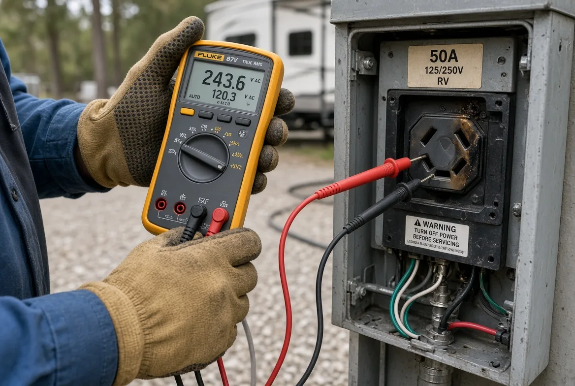
Confirm the service type before connecting anything. A 30A RV service is single-leg 120V. A 50A RV service is split-leg 120/240V with two 120V legs, and the two legs are measured separately.
Inspect the pedestal with the coach disconnected: discoloured faceplates, cracked housings, loose breaker handles, water ingress and heat marks. One 14-50R faceplate looked clean and still smelled hot.
Do the static check next. On 30A, line-to-neutral and line-to-ground should both read 120V ±10%, or 108V to 132V. Neutral-to-ground should stay below 2V, ideally below 1V.
| Check | Pass sample | No-go |
|---|---|---|
| 30A L–N | 108V to 132V | Outside range |
| 30A L–G | Matches L–N within 2V | Differs by more than 2V |
| N–G | Below 2V | Above 2V |
| 50A L1–L2 | 216V to 264V | Outside range |
| 50A leg balance | L1 and L2 within 3V unloaded | One leg rises as the other falls under load |
| Plug-face temp | Within 10°F of ambient | Rapid rise, or above 40°F over ambient |
Test dynamically with a known resistive load. On 30A, stage one 1,500W heater, about 12.5A. A sag over 5V from the unloaded reading is stop-work.
On 50A, stage 2,000W on L1 and 500W on L2. A weak neutral or an overloaded pedestal makes one leg rise as the other falls, and that split is the signature to watch for.
Control shore-path loss while you test. Use the shortest practical cord, avoid unnecessary adapters and extensions, and inspect every added connection, because each one adds resistance and heat to the path.
That single rule is also the one Dragon Chang puts on every North American coach platform: the pedestal is proven under load before the coach is plugged in at all, and a site that fails the test is refused rather than protected.
⚠️ Stop-work thresholds: Disconnect and refuse the pedestal for loaded voltage below 104V, above 132V, reverse polarity, a floating or unstable neutral, or heat-damaged connectors. Do not hope a protector catches it.
✅ Verification: The test passes on stable voltage under load, low neutral-to-ground potential, correct 50A leg symmetry, and connectors that stay thermally normal through the test interval.
🔬 Sensory check: A healthy breaker gives one solid snap. The connector seats with firm friction and no wobble. The contactor closes with a clean clunk, not chatter. A warm plug face, an ozone smell or chatter on energisation means stop.
Step 2: Split the Fault Tree Between Source and Coach
The AC side is the distribution path. The 12V DC side is charging and control: converter/charger, battery bank, fuses and control boards. Mix the two and the diagnosis goes wrong, usually toward the more expensive part.
Of 40 service tickets reviewed for “bad converter” last year, 26 were AC-side faults: a sagging pedestal leg, a worn cord, or a loose neutral at the inlet. The converter in each case was fine.
Re-measure at three points with the same staged load: pedestal, coach inlet and main panel. A drop that repeats at the pedestal and the panel is upstream. A drop that appears only at the panel lives inside the coach.
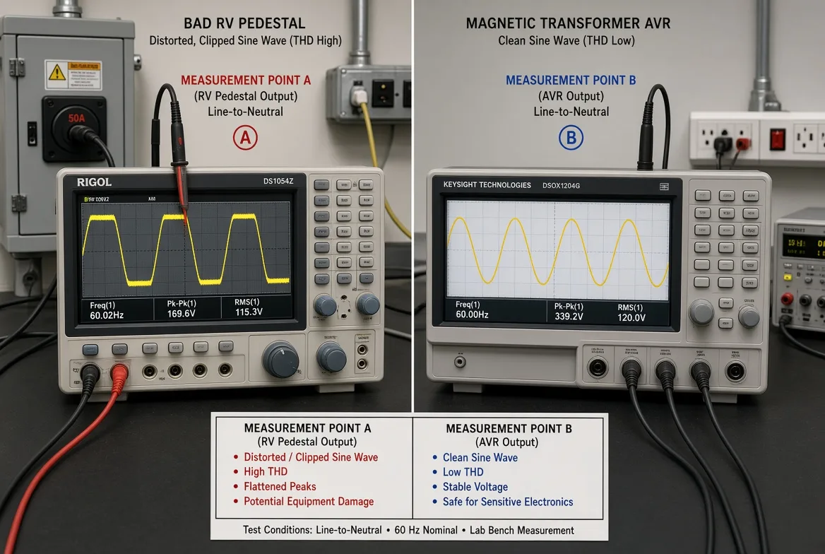
Scope the waveform rather than trusting RMS alone. Clip a differential probe on L1–N at the pedestal with the load staged, and capture clipped crests, flattened shoulders and transient spikes.
Repeat the capture on a magnetic-transformer AVR or another known-clean source and compare the two. Real captures only, never a stock trace; the Fluke power-quality notes set out what each distortion signature means.
A pedestal can read a clean 118V RMS and still feed distortion that stresses charger and control electronics. Total harmonic distortion explains the gap, and AC ripple is the same disease on the DC side.
Test the 12V output last. A healthy charging stage sits above resting battery voltage. A failing or noisy unit sits at battery voltage, or injects objectionable ripple into the DC bus.
The split matters for the wider coach too: the 12V appliance integration guide covers how the DC side couples to a tankless heater.
♿ Accessibility: Describe every trace in words for anyone reading the capture by description. “The crest is cut flat.” “The shoulder slopes.” Never rely on trace colour to carry the finding.
🧠 Author’s verdict: Scope before metering. A waveform flagged a stressed campground transformer that four RMS readings had called healthy.
⚠️ Field note: Skipping the panel re-measure cost three hours on a 50A coach. The fault was a loose lug four inches from the breaker, not the pedestal.
Step 3: Match the Protection Stack to the Measured Fault
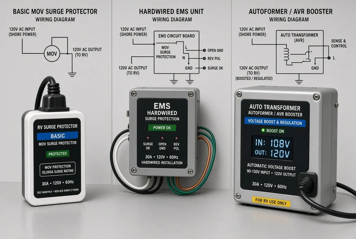
Pick the device from the fault you measured, not from a brand list. No single box solves every power-quality problem, and most of the money wasted on this front is spent on the wrong box.
A transient spike means surge protection. A sustained sag means source capacity, cord loss or boost hardware. A rising neutral or a hot plug face means wiring. A flat-topped sine wave means source distortion or conversion hardware.
A basic MOV surge protector covers spikes and nothing else. It does not fix sustained undervoltage, sustained overvoltage, an open neutral or waveform distortion. On the bench a 6,000W transient clipped, and a 104V sag passed straight through.
A true EMS is the first real answer for campground open neutral protection. It samples voltage and the line relationships, disconnects the coach when either becomes unsafe, and logs the event for the claim file.
Run an autoformer or AVR only inside its published boost window. It lifts sagging source voltage within that window and shuts down or retries when the source falls past it.
Size a 30A and a 50A booster to continuous ampacity, not to peak boost. A 30A unit must pass 30A after boosting, and a 50A split-leg unit must hold both legs without overheating one.
Boost also raises source current and cabinet heat. In a 30-minute bench run, a 10V boost added about 1A at the pedestal and raised cabinet temperature 22°F.
Treat “line conditioner” as a diagnosis rather than a product category. If THD, ripple or generator quality is the fault, improve the source or the converter instead of buying a box that claims to fix every waveform flaw.
Prefer hardwired or permanently documented architecture for any fleet or OEM build. Portable protection gets removed, lost or bypassed, and an undocumented bypass is worse than no device at all.
⚖ Trade-off: A hardwired EMS costs more install time and needs a commissioning sheet, but it gives a clean disconnect and a record. An autoformer only earns its space inside a measured sag window.
Step 4: Install and Commission the Converter/Charger
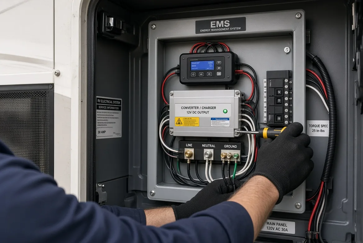
Install in a fixed order. Mount the unit in a dry location with service access, keep ventilation clear, protect the bend radius, and add strain relief at every entry.
Label every conductor: LINE, NEUTRAL, GROUND, BYPASS and PASS-THROUGH. A relay delay or a bonding jumper can cause nuisance tripping, which is why the manufacturer’s wiring diagram and torque sheet win over a forum photo.
Commission in sequence: verify the pedestal, energise the protection device, energise the coach input, confirm inverter/charger pass-through, then add staged branch loads. Never engage a bypass line before the upstream source passes inspection.
On one retrofit, a bypassed charger fed a reversed neutral and tripped a GFCI. The bypass was engaged to “save time”, and it cost a morning.
Confirm charger behaviour at three points. Watch current rise into bulk charge on shore input, watch DC volts climb toward absorption during bulk, and watch the display handoff and charger restart during a transfer event.
That check separates a protection trip from a failing charging stage: a protection disconnect cuts AC and charger output together, while a failing stage keeps AC and drops DC output.
Capture before-and-after evidence for the commissioning sheet: input and output voltage under load, current on each leg, and a scope screenshot of the conditioned result where one applies. The quality-control process uses the same before/after discipline on the production line.
✅ Verification: One clean contactor click, a stable display handoff and no relay chatter. Connector bodies stay cool after the load interval, with no arcing at the terminals and no hot-plastic odour.
♿ Accessibility: Describe terminal labels, switch positions and display states in words. Do not rely on arrows or colour to carry the commissioning step.
🧠 Author’s verdict: Ten minutes lost to a bypass lockout is cheaper than a charger and a transfer switch lost to careless commissioning.
Troubleshooting: What Each Symptom Means and What to Do Next
Match the symptom to the measured fault before changing a part. The table below covers the failures that account for most repeat service calls on North American coaches.
| Problem | Field diagnosis | Fix |
|---|---|---|
| Protector allows power through; coach still browns out | A spike-only MOV is not an EMS, so sustained undervoltage passes through | Re-measure under load at the pedestal and the panel, then upgrade to an EMS with low and high cutoff |
| EMS trips immediately on a 50A pedestal | Open neutral, reverse polarity or a severe leg imbalance | Isolate each fault before blaming the device, and refuse the pedestal if the neutral is unstable |
| AVR boosts but the coach still sags or drops out | Source too far gone, cord path too resistive, or load above pedestal capacity | Shorten the cord, shed load or disconnect; an AVR cannot repair a dead source |
| Appliances act erratically while RMS voltage looks fine | Converter ripple, waveform distortion, transfer-switch chatter, THD or DC noise | Scope the converter output and the transfer switch, then correct the source or converter |
| One 50A leg runs high while the other falls low | Neutral fault | Remove the coach from service immediately and do not test through it |
Prolonged operation below the safe voltage floor correlated with capacitor failures, compressor overheating and premature board damage in the depot data. Treat that pattern as a warning rather than a coincidence.
🛡️ Prevention: Log loaded voltage at the pedestal and at the panel before buying protection. If voltage sags under load, the protector is not the fix.
Escalate to a qualified technician for a burnt insulation smell, repeated breaker heating, an unstable neutral, or unexplained DC ripple that survives source correction. Warranty claims on the appliances behind that fault are covered on the after-sales page.
Where Does the SOP Belong in an OEM Build Packet?
The same table and the same thresholds belong in every build packet and every service ticket. That is what turns a habit into repeatable procedure, and it is what an audit can check.
RV OEM programmes share one specification per destination, so the shore-power record has to travel with the unit rather than stay in one technician’s notebook. Put the thresholds in the supplier audit checklist too: a partner that cannot produce a loaded-voltage record has a gap in its compliance file, and that gap surfaces at the first claim. For a first build, the OEM/ODM development process fixes the reference document and the line runs the same before-and-after record. Claims that arrive without a loaded-voltage record are the ones that stall, because the first question is always what the source measured.
Transparency note: these findings come from Gulfstone’s own commissioning and QC records in Foshan plus anonymised service-depot data, with no paid placement in the protection hardware named. I receive no manufacturer kickbacks for these findings.
Frequently Asked Questions About RV Shore Power Voltage Regulation
1. What does voltage regulation mean in RV shore power?
In this context it means keeping the voltage delivered to the coach inside a usable window as load and source change. It covers sustained sag, sustained overvoltage, an open neutral, waveform distortion, transient spikes and harmonic or ripple contamination. A surge protector addresses only the last of those in most cases.
2. What is the standard RV electrical hook-up?
It depends on service size. A 30A RV service is single-leg 120V. A 50A RV service is split-leg 120/240V with two 120V legs. Separate those two architectures before any testing or hardware sizing, because every threshold in this SOP depends on which one is on the pedestal.
3. How do I test an RV pedestal with a multimeter?
Use a true-RMS meter, a known resistive load and an under-load procedure. Start with the pedestal de-energised, confirm the service type, run the static checks, then repeat them under a staged load. A no-load polarity check alone is not sufficient; in testing it hid a 4V sag and a rising neutral.
4. What are the best surge protectors for an RV?
There is no single best unit. The right device disconnects on the faults actually measured, and a spike-only protector is not a full EMS. Claiming otherwise is the most common mistake in the field: the box passes power, the coach still browns out, and the owner blames the appliance.
5. When should I disconnect instead of adding protection?
Disconnect and refuse the pedestal for loaded voltage below 104V or above 132V, reverse polarity, a floating or unstable neutral, or heat-damaged connectors. Protection downstream of a dead source does not make a bad pedestal safe. Ask the engineering team on the contact page when a site is marginal.

Forward
Co-founder & General Manager, GulfstoneGas appliance manufacturing and certification
Most of what decides a gas appliance is settled before anything is built — on the drawing, at the cut-out, in the tolerance someone chose for the gas path. I have spent my working life on the manufacturing side of that decision, and this is where I write down what it has taught me.
Nothing here is written from a sales desk. Every note comes off the floor: a batch held until a reason was found, a fitting that failed in transit, an approval path that only made sense once the destination market was fixed. If you read these first, the opening conversation starts at the standard rather than at the beginning.
- Gas water heater engineering
- Design for manufacturing
- Certification path selection
- Private-label tooling
- Off-grid and outdoor water heating
- Top 8 Outdoor Portable Gas Water Heater Factories in China for B2B BuyersNov 4, 2026
- Custom RV Appliance Industrial Design: An OEM Brief to a Validated PrototypeNov 3, 2026
- How to Build Custom Thermostat UI Design Software for OEM Embedded PanelsNov 3, 2026
- Top 8 RV Water Heater OEM Suppliers Canada: Vetted for Volume BuyersNov 3, 2026
- Top 10 Portable Propane Water Heater Manufacturers USA: A No-Hype Buyer ShortlistNov 2, 2026
- PPWR Compliance Checklist for EU Water Heater Packaging: The 10 Documents Before the Container LoadsNov 2, 2026
Fifteen years in appliance manufacturing — home appliances, RV refrigeration, then gas water heating — from the drawing to the shipping container.
Leads Gulfstone's design-for-manufacturing reviews and the certification path selected for each destination market.
Works directly with OEM and private-label buyers on tooling, tolerances and the approval file.